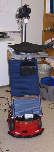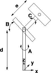

You have a mobile robot with an active imaging system. You want to build a primitive simulator so you can test out various basic vision algorithms and also more advanced issues like camera control (tracking, say). Also you want to know camera parameters in the real system, so you need to write a camera calibration program. Luckily your simulation can help....

Write a simulator that shows the image produced by the camera in u-v (horizontal and vertical) discrete image space. The input to your camera is a matrix of real-number [x,y,z] or [x,y,z,1], if you find that easier) points in LAB. Each projects to one pixel in the camera (unless it is not projected onto the CCD array).
Write a simple (or fancy, if you want) interface to let you change camera parameter values (rotate, pan, tilt, zoom) and show the resulting image. Zooming should make it bigger, panning left should make it move to the right, etc.
Just in case, write your simulator so that it can be ``called'' in a loop by a controlling program that can change parameters (in the camera: rotate, pan, tilt, zoom. In the world: position of world points) in response to something it senses in the image. For instance, it might change pan and tilt to track a single point that starts in the center of the field of view but moves over time. We might well use this simulation code in future projects so keep it flexible and reusable.
If the input to the calibration is points on a plane, the calculation simplfies (we now need only eight data points instead of eleven for the three-dimensional case). This image-plane to scene-plane mapping is called a collineation or more commonly a homography. Given the 11 variable case, the 8 variable case is trivial so you might as well do it! Again, you can make your own data for testing and debugging. Also, here are some real data of this sort, with the xyPoints.txt files having the real-world points and the uvPoints.txt files having corresponding image points.
The nice thing about the plane-to-plane case is that the image pixels map onto exactly one point on the scene plane instead of into a 3-d line in scene space. This means you can get an "inverse camera" matrix that tells where on the 2-D plane any image point is. Useful for figuring out the location of objects out in front of you if you assume their bases are on the ground plane supporting the robot.
Here's some matlab code for the (inverse) homography problem. This is just quick and dirty but shows how easy it is: MatLab Code .
Calibration: As above, with justifications that your calibration outputs are useful and correct. The inverse camera matrix for the homography case can be used to check your algorithm as well as provide useful applications.
Also turn in a README document that outlines the structure of your code: who calls what, names of modules and what they do, information on how to run the programs (arguments, data file formats, etc.).

This page is maintained by CB.
Last update: 15.8.02